Math Channels, Status Variables and Commands
Configure the source channels before building logic that uses them. A channel can come from a sensor, an ECU protocol, a CAN expansion or another calculation. Give each source a useful name and check its units. The same result can then be used by a display field, an alarm, a power output or a CAN message.
The A Complete PDM32 Configuration Example combines these features in one PDM32 setup.
Device Math Channels
Products documented with this feature: PDM32, PDM08; MXS/MXG 1.2 and 1.3, MXP/MXP 1.3, MXT 1.3 and their Strada versions; MXm, MXq, MXPS, SW4, ECULog, XLog and Solo 2 DL. The earlier MXS, MXG, MXS Strada, MXL2, EVO4S and EVO5 manuals also describe device math channels. The available calculations vary by model.
These calculations run in the device. They are separate from math channels created later in RaceStudio 3 Analysis: an Analysis calculation does not become an input to an alarm or power output in the device configuration.
Open Math Channels and choose the calculation to add.
Name the result and select the source channels requested by its settings panel.
Enter the constants, thresholds, ratios and output units required by that calculation.
Confirm the settings. Enable logging of the result if the model offers that option and the value is needed in the recorded data.
After transmitting the configuration, check the result in Live Measures.
Typical calculations include:
Calculation |
What to configure |
|---|---|
Bias |
Two compatible input channels. The ratio |
Bias with threshold |
The two channels and the threshold above which the calculation is valid. |
Calculated gear |
Engine RPM and reference speed. Complete the gear-learning procedure required by the selected device. |
Precalculated gear |
The known transmission ratios requested by the panel. |
Linear correction |
A source channel and the coefficients in |
Simple operation |
The source channels or a source channel and a constant, and the operation. |
Integer division / Modulo |
The source and divisor. Choose the quotient or remainder required by the receiving logic. |
Bit composed |
The flags to place in individual bits. SW4 documents an example that combines button states for transmission in one CAN field. |
Use the choices actually offered for the selected model. For example, the MXm/MXq manual also describes Blinkers hazard; the short list in the PDM32 manual is not a catalogue of every calculation available in RS3.
Reusable Status Variables
Products documented with this feature: PDM32, PDM08; MX 1.2/1.3 logger and Strada families; MXm, MXq, MXPS, SW4, ECULog, XLog and Solo 2 DL. MXPS has predefined status variables for its vehicle functions as well as the user variables described in its manual; the predefined variables are not freely editable.
A status variable gives a name to a condition or a sequence of states. Use it when
the same logic is needed in several places. For example, FanRequest can drive
a power output, an icon and a recorded channel without entering the temperature
condition three times.
Open Status Variables and click Add Status Variable.
Enter a name that describes the result, rather than the channel being tested.
Choose the activation/deactivation arrangement and the working mode offered by the model.
Select the source channel, comparison and threshold for each condition. Use All when every condition must be true, or Any when one is sufficient.
Set any required time qualification and the labels for the resulting values.
Enable Log values if the states must be recorded; save the variable.
Do not restrict the meaning of a status variable to a Boolean value. The product manuals document both two-state variables and variables with several output values.
Activation and Deactivation Conditions
For a Momentary variable without a square-wave modifier, using the same condition
for activation and deactivation makes the result follow that condition. If
WaterTemp > 100 deg C is the condition, it becomes false again as soon as that
comparison is no longer true. Toggle and Multistatus modes retain or advance their
state according to their own working mode.
With distinct conditions, the result can remain active between two thresholds. The PDM32 manual illustrates activation above 100 deg C with RPM above 2000, and deactivation below 80 deg C. This creates hysteresis: the variable does not change state repeatedly as the temperature moves around one threshold.
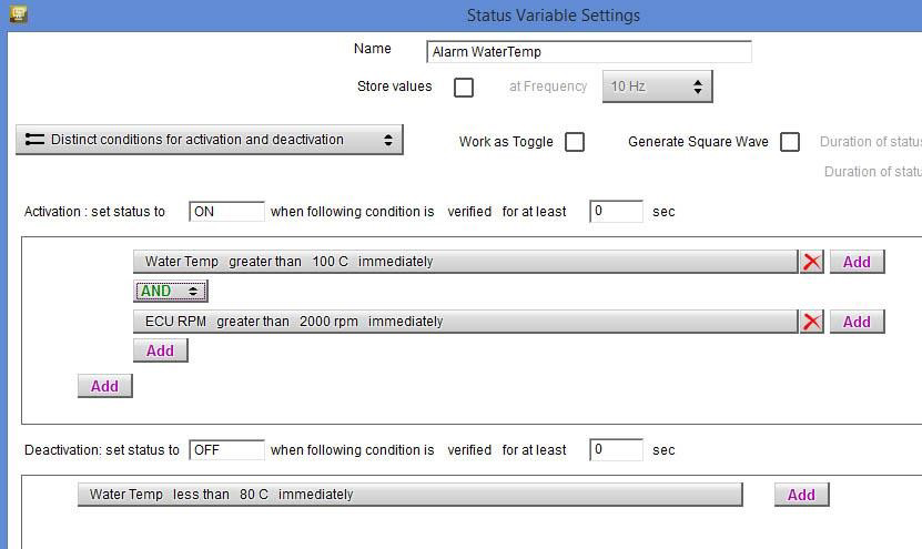
Separate activation and deactivation conditions in the PDM32 product manual. Layout and available controls can differ in a newer RS3 version.
Time qualification requires a condition to remain valid for the specified duration. Set it deliberately for both activation and deactivation where those controls are offered. The temperatures and RPM above illustrate the logic; choose operating thresholds for the actual vehicle.
Momentary, Toggle and Multiple States
Momentary: the active state follows the qualifying condition.
Toggle: each new activation of the condition changes the retained state. Holding the condition true is different from activating it again.
Multistatus: successive activations advance through the configured states. Set the values, labels and any timing required for each state.
Multiple output values, each with its own condition: select a result by testing the corresponding conditions. This is useful, for example, for converting ranges of an analog rotary-switch signal into named positions.
These are different ways of obtaining a result. Choose the one shown by the selected device and settings panel. A square-wave option, where provided, adds alternating ON and OFF periods while its enabling condition is valid. Configure both times; do not treat a status-variable square wave as an electrical PWM output.
Commands Triggered by Conditions
Products documented with these commands: PDM32, PDM08; MX 1.2/1.3 logger and Strada families; MXm, MXq and SW4. GS-Dash also documents commands through the configuration of its master logger.
On ECULog, EVO6, EVO6L, Solo 2 DL, Solo 2 DL v2 and XLog, the Commands window is not available in the release version.
A command performs an action when its condition is met. The actions depend on the device and any display or expansion selected in the configuration. The PDM32 manual describes next/previous page, the camera-input page, alarm reset and simulation of its display buttons.
Open Commands; older product manuals call this tab Trigger Commands.
Add a command and choose the action to perform.
Select its channel and activation condition. Combine conditions when needed.
Set any duration required before the condition triggers the action.
If the panel offers priorities, arrange simultaneous commands in the intended order.
Save, transmit and test both the activating and clearing conditions.
For a PDM32 with a rear-view camera connected, select the camera-page action and use the reverse-gear signal as the condition. Configure the receiving channel first, and use the gear value reported by that vehicle’s protocol. Display-button commands also require the corresponding display to be configured.
An alarm-reset command works with the alarm’s ending condition. Check that the alarm has been configured to end on the corresponding reset/button action.
Pit Event Commands
Not available in the release version
This feature is currently available in the beta version of RaceStudio 3.
When offered by the device, pit IN and OUT triggers can substitute an event condition for crossing the corresponding GPS line. Configure these commands together with the pit-lane setup described in User Pit Lane. They are separate from the normal lap-detection settings.
Sources for Configuration Logic
MX 1.2/1.3, sections 6.2.6-6.2.10; MX Strada, sections 5.2.5-5.2.9.
SW4, sections 4.1.7, 5.5-5.6 and 5.10; Solo 2 DL, configuration chapter.
Earlier device-math procedures: MXL2, section 11.1.4, EVO4S, section 10.1.4, EVO5, section 11.1.4, MXS/MXG, configuration chapter, MXS Strada, configuration chapter.