Channels, ECU Streams and Recording Settings
Start with the sources of the information that the device will use. A configured channel can feed a display, an alarm, a calculation or a transmitted stream as well as recorded data. Whether that channel is available and whether its values are logged are separate settings where the model provides both controls.
Configure Local and Internal Channels
Products documented with a Channels page: PDM32, PDM08; MXS/MXG 1.2 and 1.3, MXP/MXP 1.3, MXT 1.3 and their Strada versions; MXm, MXq, MXPS, SW4, ECULog, XLog and Solo 2 DL. Earlier MXS, MXG, MXS Strada, MXL2, EVO4S and EVO5 manuals also describe channel configuration.
A Channels page does not imply that a device has every kind of physical input. ECULog, for example, describes GPS, odometer and fuel-level channels; XLog describes internal RPM, GPS and IMU channels and can obtain analog inputs from an expansion. SW4 has channels for its controls and sensors. Select the exact model before configuring the available rows.
Open Channels and enable the source channels required by the installation.
Click the sensor, name, function, sampling frequency or parameter cell to open its available settings. Use the enable/disable icon where it is offered.
Set a recognisable name and its Function.
Choose the connected sensor, units, sampling frequency and display precision.
Fill in the additional parameters requested for that input and sensor.
Set its logging option if present. Keep a channel available to the device when its value is needed by another feature, even if its values do not need recording.
Setting |
What to check |
|---|---|
Name |
Identifies the actual source, for example |
Function |
Describes the measurement’s purpose. Function-based selectors use this information to offer suitable channels for a display or SmartyCam function. |
Sensor type |
Defines the conversion from the electrical signal to the displayed value. Select the actual sensor and its connection, rather than a sensor with a similar name. |
Measure unit |
The physical unit of the converted value. Review thresholds and downstream uses when changing it. |
Sampling frequency |
The requested rate for the channel. The usable rates depend on the device, source and sensor; choosing a higher rate does not create faster ECU data. |
Display precision |
The number of displayed decimal places. This does not increase sensor accuracy. |
If the sensor is not listed, define it as described in Custom Sensors, then select it in the device configuration.
If RaceStudio 3 says that a channel is controlled by the ECU Stream, check the intended source in that tab before changing it. For example, an RPM channel supplied by the ECU Stream cannot be configured as a separate input while that stream controls it. Confirm changes in the settings window and check the updated row.
Analog Inputs in the PDM32 Example
The PDM32 manual describes CH_IN1-CH_IN8 as selectable analog/digital inputs, CH_IN9-CH_IN12 as digital inputs, two speed inputs and a dedicated ignition input. These input names and counts belong to PDM32; use the input list for another model.
For an analog input, choose Analog, select its sensor and configure the fields above. Where offered, set the pull-up for the actual sensor circuit. For example, the PDM32 offers an internal 2 kOhm pull-up on its configurable analog inputs.
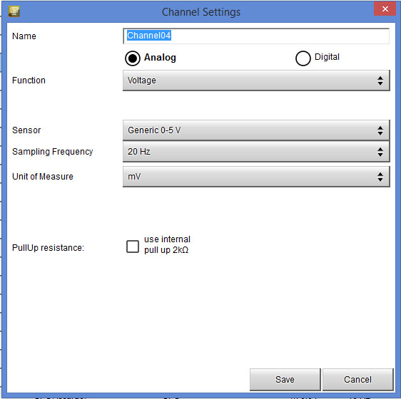
A PDM32 analog-input settings example. The available controls depend on the selected input and RS3 version.
Speed, IMU and Calibration
For a wheel-speed input, enter the wheel circumference and pulses per revolution requested by the settings panel. The MXm/MXq and Channel Expansion manuals describe coupled input modes: changing one input’s mode can also change its paired input. Review both rows after changing the mode.
Configure internal sensors only when present in the selected hardware. The MX 1.2/1.3 manual documents hardware differences in IMU and thermocouple availability; MX 1.3 installations use TC Hub for the thermocouple connection described there. An external GPS must also be connected for its channels to carry valid values.
Transmit the configuration before calibrating the sensors that require a physical zero or reference position. Use the connected device’s Live Measures and its calibration controls, as described in Devices. Observe the raw and converted values while moving the sensor through its expected range.
Select the Vehicle ECU Stream
Products documented with ECU Stream selection: PDM32, PDM08; MX 1.2/1.3 logger and Strada families; MXm, MXq, SW4, ECULog, XLog, Solo 2 DL and the earlier MXS, MXG, MXS Strada, MXL2, EVO4S and EVO5. Camera models with direct ECU input are covered in Camera, Lap Timer and Kart Settings.
Dedicated kits can use a predefined vehicle protocol. In particular, MXPS displays the ECU stream information but its manual describes the vehicle ECU selection as non-modifiable.
Open ECU Stream and click the protocol-selection control to open Choose ECU Protocol.
Choose the ECU manufacturer and model/protocol that match the vehicle and its connection. CAN, RS232 or K-Line availability depends on the device and harness. If an AiM protocol and a custom protocol have the same manufacturer and name, check the protocol type in the selector to choose the intended one.
Confirm and review the resulting channels. Enable the channels needed by the configuration; click an editable frequency to choose from the offered values.
Review the RPM and speed sources. A protocol that supplies RPM can replace the device’s direct RPM input; check which source is active.
On a CAN connection, review the bus settings described below.
Save and transmit. Check the expected channels in Live Measures before using them for protection or control logic.
If a CAN protocol is missing, create it using Custom Protocols. Match the ECU’s documented identifiers, field layout and conversions. Selecting a similarly named ECU does not establish that its data format is compatible.
When replacing a protocol, RaceStudio 3 may show Replacing CAN Protocol to match channels from the previous protocol with channels in the new one. Review this matching so references in the configuration can be updated. Afterwards, check math channels, status variables, alarms and display pages that use the changed channels.
CAN Termination and Silent Mode
The PDM32, MX 1.2/1.3 and SW4 manuals describe Enable the CAN Bus 120 Ohm Resistor and Silent on CAN Bus. Set them for the actual network wiring and communication requirements.
Enable internal termination only where that device must provide an end-of-bus termination. Review the terminations already present in the network.
Silent mode changes how the device participates on CAN. Use it only when required by the connected network; do not enable it as a general remedy for missing channels.
The CAN bus used for input and output is a shared resource. Review its settings together with SmartyCam Streams and CAN Output rather than treating the receive and transmit pages as unrelated physical ports.
Configure a CAN2 Input Stream
Products documented with a CAN2 input page: PDM32, PDM08; MX 1.2/1.3 logger and Strada families; MXPS, SW4, ECULog and XLog. Earlier MXS Strada, MXL2 and EVO5 manuals also describe this page.
Open CAN2 Stream and choose the protocol-selection control.
Select the manufacturer and model of the connected CAN module.
Review the received channels, enable those needed and select the offered rates.
Check the connector assignment and the bus settings before transmitting.
On ECULog and XLog, the EXP connector can be assigned to AiM CAN or CAN2. These are alternative uses of that connector. Assigning it to CAN2 changes the availability of AiM expansions on that connection. Choose the installation topology before adding its expansions and camera stream. SmartyCam Stream requires EXP to be assigned to AiM CAN; it is unavailable with EXP assigned to CAN2.
The CAN2 input protocol describes received messages. Outgoing messages are configured separately in SmartyCam Streams and CAN Output.
Set Lap Detection and Reference Speed
Products documenting these Parameters settings: MX 1.2/1.3 logger and Strada families; MXm, MXq, MXPS, SW4, ECULog, XLog and Solo 2 DL. Earlier MXS Strada, MXL2, EVO4S and EVO5 manuals also describe lap-detection parameters. Solo 2 and MyChron use the model-specific procedures in Camera, Lap Timer and Kart Settings.
PDM32 and PDM08 also provide lap detection and reference-speed settings in the current RS3 Parameters page.
In Parameters, review the items offered by the device:
Lap Detection: select the available GPS or optical-beacon source. GPS-based timing requires the appropriate GPS and track information. Set track width where requested. For an optical beacon, set the blanking period that rejects additional signals too close to the previous one.
Lap-time hold: controls how long the completed lap time remains displayed. It is separate from the detection of the next lap.
Reference Speed: choose the speed source used by the device. Confirm its availability and calibration before using it in gear calculations or logic.
Manage track files through Tracks for Analysis and Devices, rather than expecting an input-channel or lap-detection setting to install the track in the device.
Define When Data Recording Starts
Products documenting start-recording conditions: MX 1.2/1.3 logger family; MXm, MXq, SW4, ECULog, XLog, Solo 2 DL, MXL2, EVO4S and EVO5. Camera recording is covered separately in Camera, Lap Timer and Kart Settings. Do not infer onboard logging from the presence of a Parameters tab in a Strada display or a dedicated vehicle kit.
PDM32 and PDM08 also provide Standard/Custom start-recording conditions in the current RS3 Parameters page.
Open Parameters and review Start Data Recording.
Choose the standard conditions or the custom-condition option offered by the model.
For a custom condition, add the channel comparison and threshold. Set whether multiple conditions are combined with AND/All or OR/Any.
Configure the required duration if that control is offered.
Save, transmit and verify that the intended input values start recording.
Standard RPM and speed thresholds differ between product manuals. Check the settings of the selected configuration instead of copying a threshold from another device. Check Wi-Fi/recording behaviour for a wireless device before a test.
Sources for Channels and Parameters
MX 1.2/1.3, sections 6.2.1-6.2.4 and 6.2.8; MX Strada, sections 5.2.1-5.2.3 and 5.2.7.
MXm/MXq, sections 6.2.1-6.2.2 and 6.2.6; MXPS, sections 6.2.1-6.2.3 and 6.2.7.
ECULog, sections 4.1-4.3 and 4.7; XLog, sections 4.1-4.7 and 4.10; SW4, sections 5.1-5.3 and 5.8.
Earlier channel/parameter procedures: MXS/MXG, MXS Strada, MXL2, EVO4S and EVO5.